
 Domov
Domov
 Novosti
 Akcijska ponudba
 Popularni artikli
 Polprevodniške komponente
 Pasivne komponente
 Optoelektronika
 Konektorji
 Ventilatorji in hladilna telesa
 Releji
 Stikala in senzorji
 Napajalniki
 Baterije in akumulatorji
 Transformatorji
 Mehanske komponente
 Delovna oprema in pribor
 Vodniki in kabli
 Razvojna orodja in kompleti
 Ohišja
 Zvočne komponente
 Ostalo
Battery Charger Fundamentals
Battery Charging Basics
Li-ion chargers are devices that regulate battery charging current and voltage, and are commonly used for portable devices, such as cellphones, laptops, and tablets. Compared to other battery chemistries, Li-ion batteries have one of the highest energy densities, provide a higher voltage per cell, can tolerate higher currents, and do not have to be trickle charged when the battery is fully charged. In addition, Li-ion batteries do not have a memory effect, meaning they do not “remember” a lower charge capacity if they are charged before being fully depleted. However, Li-ion batteries must be charged with a specific constant current and constant voltage (CC-CV) charge profile that is automatically adjusted depending on the battery’s temperature and voltage levels.
Charging Profile
The charging profile is a fundamental aspect of Li-ion batteries, as it describes how a battery’s voltage and current vary while the battery is charged. For simplification, charging profiles can be organized as a graph showing time on the X-axis and battery voltage or battery charge on the Y-axes, which offers insight on how to optimally charge a battery while acknowledging safety features. Figure 1 shows the charging profile for the MP2759A, a highly integrated switching charger designed for applications with 1-cell to 6-cell series Li-ion or Li-polymer batteries.
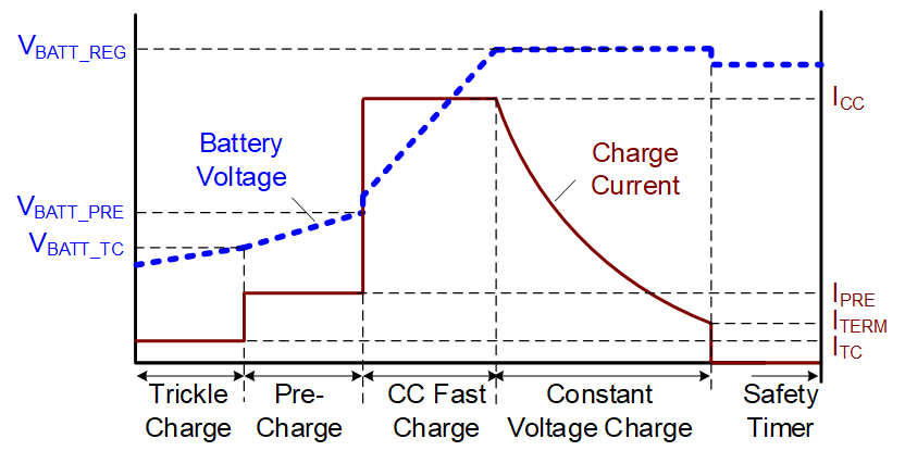
Figure 1: The MP2759A Charging Profile
Li-ion batteries follow a relatively common charging profile, described in greater detail below. Note that if a charger IC provides configurability, the designer may be able to set their own thresholds for these phases. These configurable thresholds are highly beneficial, considering that most battery manufacturers specify certain thresholds for different maximum charge current levels. Configurability can provide an added layer of safety by protecting the battery from over-voltage and over-temperature conditions, as well as overloads, which could all permanently damage the battery or degrade its capacity.
- Trickle charge: Generally, the trickle charge phase is only used when the battery voltage is below a very low level (about 2.1V). In this state, the battery pack’s internal protection IC may have previously disconnected the battery due to it being deeply discharged, or if an over-current event occurred. The charger IC sources a small current (typically 50mA) to charge the capacitance of the battery pack, which triggers the protection IC to reconnect the battery by closing its FETs. Although trickle charging usually lasts for a matter of seconds, the charger IC should integrate a timer that stops charging if the battery pack is not reconnected within a certain amount of time, as this indicates that the battery has been damaged.
- Pre-charge: Once the battery pack has been re-connected or is in a discharged state, pre-charging begins. During pre-charge, the charger starts to safely charge the depleted battery with a low current level that is typically C / 10 (where C is the capacity (in mAh)). As a result of pre-charge, the battery voltage slowly rises. The purpose of pre-charge is to safely charge the battery at a low current. This prevents damage to the cell, until its voltage reaches a higher level.
- Constant current (CC) charge: Constant current (CC) charge is also considered fast charging, which is described in greater detail below. CC charging starts after pre-charge, once the battery has reached about 3V per cell. In the CC charge phase, it is safe for the battery to handle higher charge currents between 0.5C and 3C. CC charging continues until the battery voltage has reached the “full” or floating voltage level, at which point, the constant voltage phase begins.
- Constant voltage (CV) charge: The constant voltage (CV) threshold for Lithium cells is usually between 4.1V and 4.5V per cell. The charger IC monitors the battery voltage during CC charging. Once the battery reaches the CV threshold, the charger transitions from CC to CV regulation. CV charging is implemented because the external battery pack voltage seen by the charger IC exceeds the actual battery cell voltage in the pack. This is due to the internal cell resistance, PCB resistance, and the equivalent series resistance (ESR) from the protection FET and cell. To guarantee safe operation, the charger IC must not allow the battery voltage to exceed its maximum floating voltage.
- Charge termination: The charger IC determines when to terminate the charge cycle based on the current going into the battery dropping below a set threshold (about C / 10) during the CV phase. At this point, the battery is considered fully charged and charging is completed. If charge termination is disabled in the charger IC, the charge current will naturally decay to 0mA, but this is rarely done in practice. This is because the amount of charge going into the battery exponentially decreases during CV charging (since the cell voltage is increasing like a large capacitor), and it would take a significantly longer time to recharge the battery with a very little increase in capacity.
The actual charge current at any moment can be lower than what is set due to loop regulations, such as the input current limit, the input voltage limit, thermal regulation, or battery temperature. For more information on battery safety, see the Safety section below.
Fast Charging
When it comes to fast charging, it is important to determine how much current the battery can handle based on the cell manufacturer’s specification. For example, batteries have a “C-rating,” which specifies the maximum current at which the battery is charged and discharged. The C-rating specification is typically between 0.5C and 3C depending on the exact cell employed, with tradeoffs between a higher C-rating and lower energy density. As an example, a 3000mAh battery with a C-rating of 1C means that the battery can be charged at a maximum of 3A. Usually, the cell manufacturer also specifies different voltage and temperature ranges for the C-rating, where the rating is reduced at lower voltages and both higher and lower temperatures.
If a battery has a higher C-rating, it can handle more current, and can therefore be charged more quickly. For example, portable devices, such as smartphones and laptops can benefit more from a higher C-rated battery compared to wireless speakers, since they will likely be recharged at least once per day. Usually, devices with shorter run times and constant usage are prime candidates for fast charging. Understanding the battery’s C-rating can help designers determine how to optimize their solution by enabling them to select the charger topology and safety features that best suits their battery.
The constant current (CC) charge phase — also known as fast charge — is typically determined by the battery’s voltage thresholds. In particular, the MP2731 defines its fast charge phase as the interval during which the battery voltage exceeds the pre-charge threshold, and is less than its CV threshold. During the first fast charge stage, the battery FET charges the battery with a fast charge current. Once the battery voltage exceeds its new threshold, the battery FET is considered fully on.
How to Select A Charger
When choosing an appropriate battery charger system, it is important to consider the following parameters: battery pack series cell count, input voltage (VIN) range, charging current, and system power path management. These parameters dictate what type of power conversion is required by the charging circuit (switching or linear), and what additional features are required to power the system rails, such as narrow-voltage DC (NVDC) power path management. The answers to these questions directly drive the charger topology selection. In short, the charger topology can be determined by the following basic parameters:
- For a single-cell battery pack with a 5V input and a charge current below or equal to 500mA, choose a linear charger. In general, single-cell battery packs have a maximum voltage between 4.2V and 4.5V. Note that depending on the system’s design and thermal performance, a linear charger may have an maximum current that is above or below the expected value.
- If the charge current exceeds 500mA, it is recommended to use a switching charger. Switching chargers are also recommended for USB applications, which generally have voltages equal to or exceeding 5V. There are three switching charger topologies to choose from based on VIN and the maximum battery voltage (VBATT). If VIN is below the maximum VBATT, choose a boost charger. If VIN is greater than or equal to VBATT, choose a buck charger. If VIN is greater than, less than, or equal to VBATT, choose a buck-boost charger. These topologies will be described in greater detail below.
Battery Pack Cell Configuration
In terms of battery configurations, there are single-cell chargers and multiple-cell chargers. These values correspond to the number of cells physically placed in series inside of the battery pack, as well as the charger’s output voltage (VOUT) range.
Single-cell batteries have a lower power output and a smaller size — typically, the maximum discharge current is between 1C and 3C (e.g. 1Ah = 1A to 3A). This means that single-cell chargers are often used for smaller mobile devices, such as phones, watches, and headphones. On the other hand, multiple stacked cells can deliver significantly more power, and are often used for larger systems that demand more power, such as notebook computers, speakers, power banks, and drones. Note that the number of cells connected in parallel inside the battery pack do not typically affect charger IC selection since their voltage is the same.
Input Voltage (VIN) Range
Most consumer electronics are powered from USB ports, which must support 5V at minimum. As the USB standard has evolved to the new USB Type-C connector supporting USB power delivery (PD), the maximum allowed voltage has increased up to 20V. This value will rise up to 48V with USB PD extended power range (EPR) specifications. From the charging system design perspective, the charger IC must be able to support the VIN range and power required to charge the battery while powering the downstream rails. If the total power needed by the system is below 15W, then a standard USB Type-C with 5V can be used. If the total power exceeds 15W, then a solution with a higher VIN and USB PD must be employed when using a USB connector.
For USB applications, the charger IC must be backwards compatible with 5V, which can add some cost and complexity to the charger selection when using a battery with more than 1 cell in series, since the topology will have to a support wide input range (e.g. buck-boost). If a non-USB connector is used (i.e. a barrel jack), the system designer typically has the freedom to select VIN without having to support other voltage levels. This makes the design simpler and more cost-effective, but it may be more inconvenient for the end user, who will need a special wall charger that is only compatible with the particular product.
Charge Current
Designers should consider the charge current and how it relates to charger topology selection. If the charge current is less than or equal to 500mA, a linear charger is recommended due to the reduced cost and size. Switching chargers are recommended for higher currents since they reduce power loss and increase efficiency; however, switching chargers require an inductor and take up additional board space compared to linear chargers.
For example, when charging from a 5V USB input at 1A, a linear charger is not recommended. When using a linear charger, there is 2W of power loss when the battery is 3V at the start of the fast-charge phase, since 2V is dropped across the charger. Linear chargers are only recommended for small batteries with lower charge currents, while switching chargers are able to handle much higher charge currents.
System Power Path Management (PPM)
Power path management (PPM) adjusts the battery charge current based on the input source current capabilities and the system load current requirement. PPM helps the system microcontroller (MCU) or system-on-chip (SoC) receive sufficient power while using any excess current to charge the battery. There are a few power path options, described below.
Simple Chargers without a Power Path (Direct Battery Supply)
For simple chargers without a power path, the battery is directly connected to the system, and the charger IC only has one output, which is the battery. In this scenario, the battery must be charged to reach the minimum system voltage before the product can power on. This can take extra time when the battery is deeply discharged, which can result in a suboptimal user experience in applications where the product can be used while charging. The advantages of a simple charger without a power path are its simplicity and lower BOM cost.
One example of a simple charger is the MP26029, a single-cell Li-ion/Li-polymer battery charger IC with thermal regulation (see Figure 2). The on-chip charging MOSFET works as a fully featured linear charger with pre-charge, constant current (CC) charge, constant voltage (CV) charge, charge termination, and auto-recharge. The internal bias circuit is powered by the higher voltage between IN or BATT. The MP26029 also provides an ISET pin to enable or disable charging, as well as a status indication pin to report when the device is actively charging, has finished charging, or if charging has been suspended.
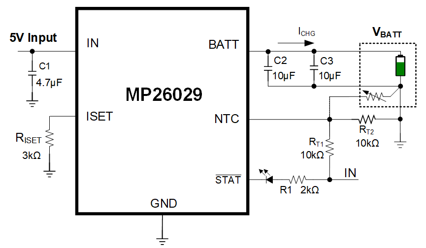
Figure 2: MP26029 Typical Application Circuit with 5V Input
OR Selection Power Path (Bypass Mode)
For OR selection power path management (also called bypass mode, or the pass-through approach), external switches manage the battery charging and system paths. This method optimizes energy storage capacity and provides protections in the event of a battery failure. OR selection power path management follows two basic principles:
- When VIN is present, VIN is directly connected to the system
- When VIN is absent, VBATT is directly connected to the system
With OR selection, the system must be able to tolerate VIN. Meanwhile, the system voltage (VSYS) is not regulated. In addition, with this topology, the battery cannot supplement the system power with additional current, since these two rails are separate. NVDC power path architecture, which can mitigate this issue, is described further below.
The MP2759 is an example of an Li-ion/Li-polymer battery charger with OR selection power path management that can work with 1 cell to 6 cells, which allows it to support several battery chemistry types with different battery regulation voltages. The MP2759 is available in a QFN-19 (3mmx3mm) package, and is able to switch between four charging phases — trickle charge, pre-charge, CC charge, and CV charge — depending on the battery’s voltage and current. It features OR selection to power to the system when the battery is depleted, as well as protections, such as battery thermal monitoring with a JEITA profile and battery over-voltage protection (OVP).
The MP2759’s external P-channel battery MOSFET supports OR selection power path management. The battery FET’s gate is driven by the IN pin’s signal. When an input source is absent, the battery FET connects the battery to the system. When an input source is present, the battery FET turns off, and the input source powers the system through a different MOSFET (Q1). In addition, the input current limit prevents the input source from being overloaded by reducing the charging current (see Figure 3).
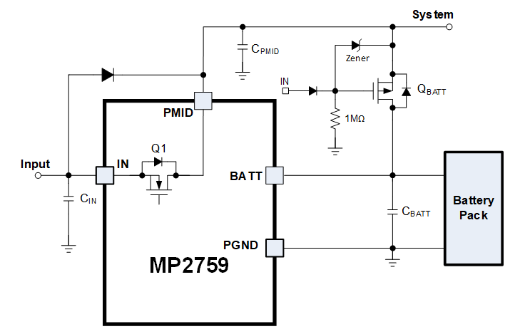
Figure 3: OR Selection Power Path Management
Narrow-Voltage DC (NVDC)
Narrow-voltage DC (NVDC) power path management is a common method that provides a number of benefits, described below:
- The system can instantly power on with a low battery voltage
- The system voltage tracks the battery voltage to reduce the charging thermals and allow for a lower voltage system design, since it does not need to tolerate the external VIN
- The battery can supplement the system when the input power is low
- The system can be fully disconnected from the battery for use cases, such as shipping mode, over-current protection (OCP), or under-voltage protection (UVP)
With NVDC, the charger has two separate outputs (one from the system and one from the battery), which allows the charger to regulate the system above the battery voltage. NVDC also provides the option for shipping mode. In shipping mode, the battery can be completely disconnected from the system output when VIN is absent by disabling the internal battery FET located between the battery and system nodes. This effectively eliminates current consumption by the system when the product is sitting on a retail shelf, which prolongs the battery’s charge.
The MP2733 is a highly integrated switch-mode battery charger for single-cell Li-ion and Li-polymer batteries. This device provides NVDC power path management, which makes it well-suited for tablets, wireless cameras, smartphones, and portable devices. With NVDC, the system and battery are controlled separately, which gives the system priority at start-up, so it can turn on with a missing or deeply discharged battery. If the input power is available with a depleted battery, the system voltage is regulated to its configurable minimum value (VSYS_REG_MIN). The NVDC architecture is supported by a front-end, step-down DC/DC converter and a battery FET placed between the SYS and BATT pins. Figure 4 shows the MP2733’s NVDC structure.
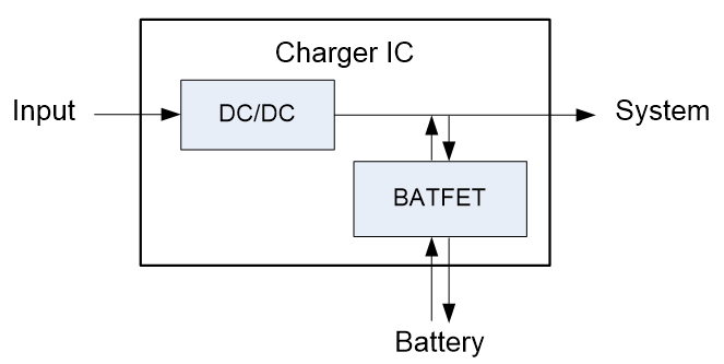
Figure 4: NVDC Power Path Management Structure
The NVDC structure regulates the voltage in the following ways:
- If VBATT drops below VSYS_MIN, the system voltage is regulated to VSYS_REG_MIN. Meanwhile, the battery FET works linearly to charge the battery based on VBATT. In addition, VSYS_MIN can be set via the I2C interface.
- If VBATT exceeds VSYS_MIN + VBATT_GRD (about 60mV), the battery FET fully turns on. The voltage difference between the battery is the VDS of the battery FET, and the charge current loop is implemented by the converter’s PWM control.
- If charging is suspended or completed, the system voltage is regulated to its maximum value (see Figure 5).
In addition to the features mentioned above, the MP2733’s NVDC structure supports shipping mode.
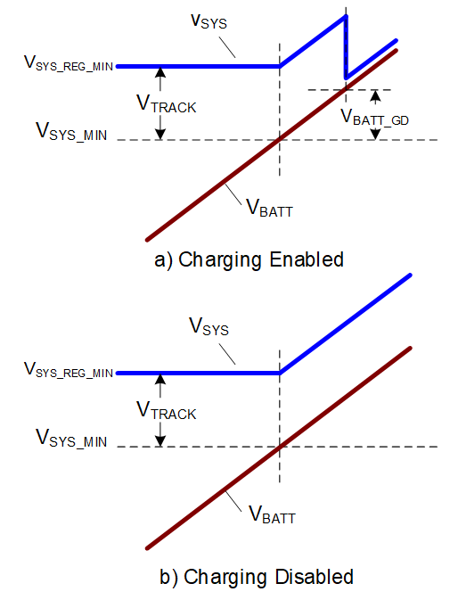
Figure 5: VSYS Variation with VBATT
Charger Topologies
The two main types of charger topologies are linear chargers and switching chargers (which can be further categorized into boost chargers, buck chargers, and buck-boost chargers) (see Figure 6). These topologies are described in great detail below.
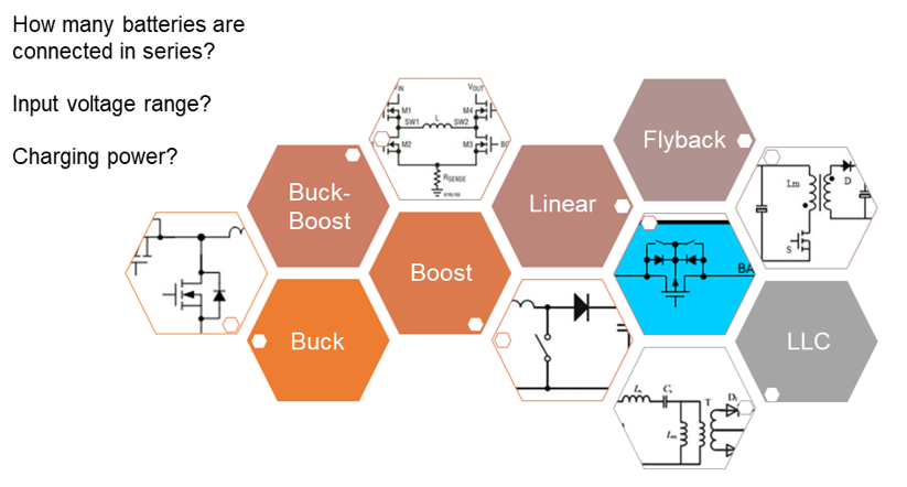
Figure 6: Charger Topologies
Linear Chargers
Generally, linear chargers are small, simple, and cost-effective. These chargers reduce noise because there is no switching, but higher charge currents lead to higher power dissipation, which is limited by the package size. This makes linear chargers ideal for portable Internet of Things (IoT) devices (e.g. fitness accessories, smartwatches, and Bluetooth earbuds) due to their small size.
An example of a linear charger is the MP2662, a highly integrated Li-ion/Li-polymer battery charger with power path management for portable applications. In its ultra-compact WLCSP-9 (1.75mmx1.75mm) package, the MP2662 can take power from either an AC adapter or a USB port for flexibility, and the device autonomously determines whether it should be powered by the input, the battery, or both. The MP2662’s power path management separates the charging current from the system load to provide charge termination and ensure that the battery remains in full-charge mode. An integrated I2C interface allows the device to be configured for various safety features, including battery under-voltage lockout (UVLO), input current limit, minimum input voltage regulation, charging current, battery regulation voltage, and safety timer.
Switching Chargers
Switching chargers are more efficient than linear chargers at medium to high currents, and provide more adaptability across wide input voltage (VIN) ranges. However, switching chargers also require an inductor and more capacitors, which can increase cost, complexity, and take up more PCB space. It is recommended to choose switching chargers for applications with larger batteries, or applications that need higher efficiency for fast-charge capabilities. These chargers are ideal for high-density systems, such as smartphones, tablets, notebooks, power banks, and speakers. There are primarily three different types of switching chargers: buck (or step-down), boost (or step-up), and buck-boost chargers, which can regulate the output above or below the input. When choosing a switching charger, consider the following two questions:
- What is the VIN range (e.g. is it for a 5V USB application, or a USB PD application)?
- What is the battery pack voltage range (as determined by the number of series cells in the pack)?
Once these questions have been answered by the system designer, the switching charger topology can be easily identified. Typically, switching chargers are used for applications with charging currents above 500mA.
The types of switching chargers (buck, boost, and buck-boost) are described below.
Buck Chargers
Buck chargers are implemented when the minimum input voltage always exceeds the maximum battery voltage (VBATT), such as a 5V USB with a single-cell battery. Even if the maximum charging power needed exceeds 15W offered by 5V USB Type-C (e.g. most smartphones), a buck charger can still be employed as long as it can handle the higher VIN operating level and power supported by USB PD.
The MP2721 is a buck charger that provides a low-impedance power path to optimize charging efficiency, reduce battery charging time, and extend battery life. This device supports USB Battery Charging Specification 1.2 (BC1.2) and non-standard adapter detection. The MP2721’s I2C interface can configure parameters, such as the output voltage (VOUT), switching frequency (fSW), charge current, input current limit, safety timers, and die temperature regulation.
Boost Chargers
Boost chargers are implemented when VIN is below the maximum VBATT, such as a 5V USB with a 2-cell battery. This type of charger is only implemented for applications requiring ≤15W, since a buck-boost charger would be required for higher power demands. Using a boost charger for multi-cell applications with lower power demands can save cost by eliminating the need for additional components, such as a USB PD controller.
The MP2672A is a flexible switch-mode boost charger IC for Li-ion batteries with two cells in series, which makes it well-suited for portable applications, such as point-of-sale (PoS) systems, gimbals, and Bluetooth speakers. This charger features a cell balance function that monitors the voltage of each cell and equalizes the voltages if they exceed the mismatch threshold. In addition, the MP2672A has two configuration modes: standalone mode and host-control mode. In host-control mode, the charging parameters can be configured via the I2C, while standalone mode allows certain parameters to be adjusted by connecting resistors to the CV and ISET pins. Protection features include battery over-voltage protection (OVP), a safety timer, a watchdog timer, missing battery detection, and thermal regulation.
Buck-Boost Chargers
Chargers with a buck-boost topology allow VBATT to be above, below, or equal to the device’s VIN, meaning the battery can continuously be charged with any power source voltage level until it reaches its target voltage. This makes fast charging possible across a very wide range of conditions, though it does necessitate a larger charger IC package size. Typically, when input power is present, a buck-boost charger can operate in three operating modes: boost mode, buck mode, and buck-boost mode. In boost mode, VIN is below VBATT. In buck mode, VIN exceeds VBATT. In buck-boost mode, VIN is almost equal to VBATT. Buck-boost chargers can deliver high power across the complete PD voltage range, while also offering backwards compatibility with 5V legacy USBs. These chargers are most commonly employed in multi-cell series USB PD applications, such as notebook computers, smartphones, and power banks.
The MP2760 is an optimized buck-boost charger in a TQFN-30 (4mmx5mm) package. This charger features narrow-voltage DC (NVDC) power path management and USB On-The-Go (OTG) or USB PD source mode. USB PD source mode allows USB devices (e.g. a power bank) to act as a power source, so that other USB devices (e.g. a smartphone) can be charged from it.
The MP2760 is designed for battery packs with 1 cell to 4 cells in series. It provides four switching FETs and integrates two N-channel MOSFET drivers for input voltage pass-through and NVDC control. Its safety features include battery over-temperature protection (OTP), system and battery OVP and under-voltage protection (UVP), missing battery detection, and short-circuit protection (SCP).
USB On-The-Go (OTG) or Source Mode
USB On-The-Go (OTG) (also known as USB Type-C source mode) is not a new feature to USBs, but it was not common before the USB Type-C connector was introduced. USB OTG allows for bidirectional power from a portable battery powered device, which enables a device (e.g. power bank) to charge other connected devices or accessories. Previously, older micro USB specifications required a special cable to take advantage of OTG, which increased costs and inhibited product interoperability (e.g. a cable supporting OTG may not be compatible with charging other devices). Once the USB Type-C standard was released, USB OTG became a much more popular feature, since it could be implemented with the same cable and connector without adding much cost. Today, many switching charger ICs with inductive topologies support USB OTG operation. This feature can be found in many common products, such as notebook computers, smartphones, and power banks.
There are three main requirements for a product to support USB OTG:
- The charger IC must support bidirectional operation, with at least 5V available.
- The charger IC must have a current limit function to protect attached sink devices from drawing too much current.
- The product must have a USB CC controller that can change roles from a sink (power consumer) to a source (power provider), detect an attached sink, and advertise the source’s rated current on the CC pins.
The MP2722, a high-efficiency buck charger, integrates the required functionality of USB Type-C source mode and dual-role power (DRP) mode. The device’s integrated CC controller provides sink-only mode, source-only mode, and DRP mode. These modes can be set manually via the I2C, or they can be selected automatically. The MP2722 is fully compliant with USB Type-C 1.3 with DRP functions, as well as Try.SNK and Try.SRC mode support.
In sink-only mode, the device can sink power from an input source. The device acts as a charger only, and charges the battery when there is an input source on the IN pin.
In source-only mode, the device can source power to the IN pin using the battery. This mode is useful for applications that want to power up external devices.
In DRP mode, the DRP port acts as a sink or a source, and automatically toggles between these functions according to the port type that has been plugged in. Regardless of how the DRP port functions, the host can force the device to turn on and off.
Safety
In addition to determining the ideal battery charger topology, designers must also consider a device’s safety features, and how those features are relevant to the overall solution. Common safety features monitor and provide protections for:
- Input, battery, and system under- and over-voltage conditions
- Input, system, and battery over-current conditions
- Battery charging current and voltage profile
- IC temperature and battery temperature (including JEITA standards)
- Charging/discharging time limits (via charging safety timer)
- The MCU and charger software (via watchdog timer)
The general method of implementing safety features in a battery charger IC is to have both a regulated operation range (e.g. current and/or voltage) and limits above and below which charging or device operation is not allowed.
For example, if the expected operating input voltage (VIN) is 5V, then the charger IC may set a 3V input under-voltage protection (UVP) threshold and a 6V input over-voltage protection (OVP) threshold. If VIN moves outside of these thresholds, the IC disables power from the input. The charger IC may also implement a configurable VIN regulation loop at about 4.5V to prevent excessive power from being drawn from the input supply. In this scenario, the charger IC simply draws as much power as needed from the input; when VIN drops below its threshold, the power drawn is reduced. When this regulation loop is combined with under-voltage lockout (UVLO) and over-voltage lockout (OVLO) protections, the charger IC can safely maximize input power while the device is plugged in and valid.
An example of a battery charger IC with robust protection features is the MP2651. This buck-boost charger provides cycle-by-cycle MOSFET current limiting, system and battery OVP and UVP, system short-circuit protection (SCP), thermal regulation, missing battery protection, and battery temperature monitoring. It also monitors the battery current to ensure that the battery is not deeply depleted.
The MP2651 also provides a safety timer to prevent prolonged charging cycles. For constant current (CC) and constant voltage (CV) charging, the timer starts when the battery enters the CC charging phase. The timer can be reset under various conditions, such as when the input power is toggled or when the device recovers from thermal shutdown. The timer can also be suspended if the battery enters supplement mode or there is an NTC hot or cold fault. In addition, the timer can be extended to be twice its original length.
Watchdog Timer
The main purpose of a watchdog timer in a configurable charger IC is to safely handle instances during which the system’s microcontroller (MCU) freezes or stops responding. If the MCU begins acting erratically or stops functioning altogether, it can potentially cause incorrect values to be written to the charger IC, which could affect battery safety during charging.
When enabled, the watchdog timer runs for a configurable period of time. When the charger IC sees an I2C transaction from the MCU, the watchdog timer is considered to be “pet,” and the timer resets again. Under normal operation, the timer is consistently pet before it runs out. If the timer is allowed to expire when there has not been an I2C transaction, the watchdog timer triggers a “bark.” If a bark occurs, the charger sends an interrupt to the MCU, and then it starts a second-level timer. If there is still no I2C transaction before the second-level timer expires, then there is a “bite.” In this scenario, all of the charger IC’s registers are reset to their default values, and the charging is disabled for safety. In some charger implementations with an NVDC power path, a watchdog timer bite can forcibly toggle the battery FET to cut power between the charger IC and MCU, then restart the MCU.
The MP2710 is a compact 1-cell battery charger IC with power path management and an I2C interface. This charger features a configurable watchdog timer that works in both charge and discharge mode, though the timer can be disabled in discharge mode to reduce quiescent current. If the watchdog timer is enabled in host mode (when changes are being made to the configurable parameters), the host must reset the timer regularly by writing to the MP2710. If this timer expires, most of the device’s registers returns to their default modes. If the timer runs out in both charge and discharge mode, the low-dropout (LDO) FET and the battery FET turn off for 4s. The watchdog timer can be disabled or set to 40s, 80s, or 120s, and it can be reset via the I2C.
Battery Temperature Monitoring and JEITA
A critical safety requirement for a charger IC is the ability to monitor the battery’s temperature during charging and control the charging current (and/or voltage) when the temperature is outside of a specified range. In the simplest implementations, a charger IC provides two comparators with hot and cold thresholds that relate to a proportional voltage seen across one or more negative temperature coefficient (NTC) resistors inside of the battery pack. When the battery pack’s temperature exceeds the hot threshold or drops below the cold threshold, charging is disabled.
In more advanced implementations, a charger IC may implement five or more temperature windows that are based on the Japanese Electronics and Information Technology Industries Association (JEITA) battery standard. JEITA reviews and confirms standards for technical reports, and the groups’ battery standard is widely used across the industry. In many implementations, a charger IC should not only make each temperature threshold configurable, but it should also implement configurable responses for each threshold, such as reductions in charge current or the maximum battery charge voltage, or disabling charging completely. This configurability is vital because most battery pack manufacturers specify unique charging current and voltage requirements for each cell type and temperature range.
The MP2651 is a 1-cell to 4-cell buck-boost battery charger that implements a fully customizable JEITA profile with four temperature thresholds and five windows. Known as the cold, cool, warm, and hot thresholds, the default power-on thresholds and charging behavior can be configured via the one-time programmable (OTP) memory and be modified later by the I2C. These thresholds are monitored via the voltage ratios between the VNTC and NTC pins, where every voltage corresponds to a particular temperature of the NTC resistor in the battery pack. Adding further insight into the battery’s temperature at any given time, the MP2651 implements an analog-to-digital converter (ADC) that monitors the NTC pin and other key parameters. With all of this monitoring functionality, the MP2651 achieves JEITA compliance while providing additional battery temperature information and flexibility to safely accommodate different batteries.
Conclusion
MPS’s battery charger solutions cover a wide range of high-performance ICs that can complement any battery powered application from single-cell chargers to battery chargers with two series cells or more than three series cell chargers. There are many variables to consider when deciding on a battery charger IC, such as the charging profile, charger topology (e.g. switching or linear chargers), power-path management structure, battery cell configurations, and safety features (e.g. watchdog timer and JEITA temperature monitoring). Once a designer understands how these parameters affect their system and the specifications of their battery, they will be able to select the optimal battery charger IC.
Vir: https://www.monolithicpower.com/battery-charger-fundamentals